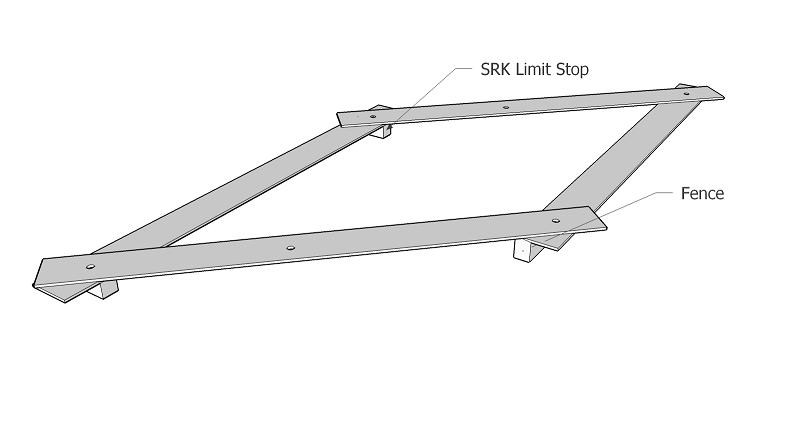
This thread was originally posted on SMC by Kevin Pauba. It is here with his permission.I was thinking about having an adjustable fence on the PBB that would stay parallel, be simple to operate and easily removable. Well, my simple mind came up with this simple answer (see image). One side clamps to the long SMEs (using the EZ small connector) so that it's held in place. The other is free to move and is constrainted to move parallel to the fixed side. The angled pieces that move between the two sides can also be clamped with knobs so that the whole parallelogram is made rigid.
To "calibrate it", you would loosen the clamps and extent it to it's maximum width (mine would be about 18") so it would reach from the edge of the rail and span the distance to the outermost edge of the SMEs. You would then tighten the clamps after first holding (clamping) the movable side to the rail.
Both sides will then be parallel to the rail. Now you can measure the width of the rip from the blade to the movable side, lock the fence into place by tightening the knobs on the intersection between the movable side and the connecting members.
Probably a bad description but I would like all you bright ones to critique the idea.
 Dino Makropoulos Replied:
Kevin,
One of the best (if not the best idea so far)
SMART TOOLS FOR
and by SMART PEOPLE.
 another way to "calibrate it"
Remove the white edge.
Push the fences against the rail.
Lock the movable fence with two connectors.
Move the stationary fence to max. Lock the stationary fence with two connectors.
Think about the SME extrusion upside down and 4 connectors.
Peter West Replied:Great idea,
- but but I wonder what the maximum practical width of cut would be and if this would be practical for cuts of say 6ft in length (for mid-height cabinets for example) or even 2ft 6 inches (base cabinet height).
If my calculations are correct, the front rail of the parallelogram fence would have to be close to 11ft long - (depending on the width of the table) - for 6ft cuts, and 8ft for 2 1/2ft cuts to allow it to be calibrated to the rail and then 'swung' so it was still overhanging the front squaring SME when making cuts of these lengths.
Maybe I've miscalculated

, or maybe there is a way of making this work for the longer length cross cuts with a shorter front rail on the fence.
Kevin L. Pauba Replied:I agree, the fence I showed doesn't work well for larger swings (ranges). I was thinking more of cutting stiles, rails, drawer components rather than cabinet sides, backs or bottoms.
But ... I have another thought that might work well for swings up to 4 ft along the lines of a scissor jack ... I'll draw it up and submit it for review.
I also have an idea for a fence who's length of travel is limited only by the size of the table but it will take quite a bit more sketchup work to present the idea effectively.
Dik Harrison Posted:  Great concept.
Kevin,
I agree with Dino, great idea. I'm going to have to fiddle with it in SketchUp to see if I can incorporate it into any of my stuff.
Kevin L. Pauba Replied:
Here's a rough design of a "scissor fence". The fence stays parallel and aligned with the table (instead of swinging off the table). It would have close to a 48" range.
I would bet that and indexable stop could be fashioned between the movable fence and the parallel one that's anchored to the SMEs -- might be useful for something like repeatable cuts.
 Burt Wadell Replied:
I see the parellogram concept as being good for some applications. Peter has a good point with the lengths that could be required.
The sissors fence, I would consider as very questionable. As the fence extends to cut narrow pieces, the cross bars become closer together on both rails. Unless there is exceptional support, the rails can flex and cause problems.
I've done some work creating "L" fences by placing a piece of connector in a piece of SME on the table top. A second extrusion is attached to the connector to serve as a fence and a brace is needed to run from the end of the connector to somewhere on the second extrusion.
In recent tables, I have also used the easy cutting rails in the top of tables. I like having the two tracks to work with. I have positioned them carefully and been able to use the EZ Square on a table as both a cutoff stop and a rip fence.
I think that in the final analysis, we're going to end up with something that uses one or two extrusions in the table top along with connectors to creat a fence.
Burt
Bruce Benjamin Replied:This looks like a very good and creative idea, Kevin. The only possible issue I see with it is that all of the pivot points would have to be very tight and precise. Meaning, if there's any slop or play at all you would lose any of it's benefit. Even the slightest amount of play in even one of the pivot points would allow for some misalignment of the fence, thus negating it's benefit. Very precisely fitting holes and pivot bolts/screw, maybe using some snug fitting bushings would be required. I think that the bushings might be a requirement because if you just drilled holes, even if they were very precisely sized, they would eventually elongate and allow for a little bit of play. Any play would show up in the alignment of the fence as you used it and moved it. You'd have to check it every time and that's no better than just sliding the standard fence. Another requirement could be that the extension arms need to be very
rigid. The farther you have it extended the more likely there is to be some flex in the arms, thus adding another source of misalignment. The triangular nature of the extension arms naturally make it a stable mechanism but if there is a little bit of resistance at a tight pivot point, (because of tight tolerances) this might cause a slight bit of flexing in the arms. But if you can make the pivot points precise enough and the arms rigid enough, (not easy I'm sure) I see this as a
great idea. Good luck!

Bruce
Kevin L. Pauba Replied:
Burt & Bruce ... I appreciate the critique; especially from those of you with much more experience than I. I understand the need for fairly precise fits. I was planning on using bushings or bearings but wish I had a CNC machine to get the center locations accurate (hope to do that on the EZ sometime).
I didn't think there would be much load on the fence since I would expect it to be used more as a stop where the piece wouldn't be forced against the fence as it would with a TS. When I use the stops on the SRK, I take special care not to use excessive force when I run into them. I would do the same with the fences shown below.
I was also thinking that with the scissors fence I could attach a digital caliper between the fixed SME and one of the cross members (arm) and make a poor-mans digital fence (although I would have to program a microcontroller to read the serial caliper data, adjust for nonlinearities and display the actual distance on a LCD). What a great winter project!
I'll prototype the idea (probably in plywood and steel/brass). Heck, my woodworking abilities are at such a low level that a flex of 1/8" wouldn't affect the outcome of my projects

.
I need to get working on the sketchup of the other fence I have in mind that would accomodate the entire table (one axis only). Maybe I'll be able to post something this weekend. It doesn't have the error buildup problem that the scissors fence has.
David Epperson Replied:Dang this looks familiar. Several years ago I designed a system to change the width of an airflow chamber by moving the walls in on either side. Parallelism was a concern in that design as well. Without going into a full Sketchup tutorial (which I would have to take before I could write it

), it was set up something like this >->=<-< where each <-< is a pair of linkages each with two arms with a pivot in the center and at either end forming 2 parallelograms to either side of the center, and the = in the center represents an electric screw drive "cylinder". That way both walls could be adjusted individually or together to modify the width of the chamber simply by an operator adjusting the length of the screw drive actuator.
Dik Harrison Replied:One way to eliminate flex if the scissors fence would be to have a locking knob at each end of the fence to lock it down to the SMEs once it was in place.
Bruce Benjamin Replied:This part I was assuming was part of the original design. I'm considering the flex that might occur as the fence was being moved. There's not likely to be much movement but if it's only 1/16" then that's error introduced into the fence. If the slightest error in the Smart Square causes problems then the same thing would happen with an error in this scissors mechanism. This isn't something that can't be overcome but with all of the leverage of those long arms combined with all of those pivot points, well, I see a lot of room for error in the fence's final position. If my table saw fence is out of square by only 1/32" I notice it in the final product.
(fortunately, it's always dead-on square) I'm sure there is the potential for that sort of error with all of those moving parts. I'm really looking forward to seeing how he gets it working. Cool and challenging project!
Bruce
Kevin L. Pauba Replied:
I created a quick prototype and I think it worked out reasonably well.
I took four 24" strips of hardboard (about 2" wide), put some glue at the very end of the long strips and clamped them together into a 4-layer sandwich. After about an hour I drilled holes (5/16" dia) at the two ends (20" apart) through all four layers. I then trimmed off the last inch or so off each end where the glue was to separate all of the strips. I glued a 3/4" x 1" scrap to one of the strips to act as a fence.
I tapped in bronze bushings (1/4" ID, 5/16" OD) at the four revolute joints (see attached diagram). Threaded knobs with 1/4" male studs were used to connect all of the joints.
As I was building the fence, I realized that the SRK limit stops that ride on the rail would work
perfectly to attach one side of the parallelogram. This allows the whole parallelogram to slide along the rail and is easy to remove and attach back onto the rail. It's also easy to reverse to use the fence on the other side of the rail.
I made several cuts with the fence and found that over a 48" length, I was off 0.040" (less than 3/64"), 0.024" (just greater than 1/64"), 0.052" (a little more than 3/64") and 0.044" (just about 3/64"). The width of cuts were 1.5", 8", 12", 16".
I would have liked to see the deviation to be less than 1/32" but I think I can get better performance and repeatability with UHMW plastic and more careful fabrication techniques. I bet Dino could do even better
.
I really like having the fence use the SRK limit stops to attach to the rail. It allows the me to easily remove the fence when not needed and allows it to easily slide into position. I think there should be some adjustability on the fence that is attached to one of the sides so that it can be made exactly parallel to the fence (my gluing was just a little bit off). The reach of 18" or so on this fence is a little small -- double that would be nice but I think the length of the side that attaches on the rail (and the one opposite) should stay at (or less than) 24" or so.
I'm sorry I don't have pictures -- my daughter borrowed my memory card to take more pictures of my new granddaughter.
It would be great if a number of you built your own and reported on the construction techniques and performance of your parallelogram fence.
 Michael Schwartz Replied:
I think I will build one of these for my PBB
Best fence Idea since Burts EZ Uni.


