This thread was originally posted on SMC.I Posted:PBB begun at last...
I finally came up with a reason to put other things on hold and build my PBB. I need to make some narrow tapered strips to aid in trimming out a window that is not co-planer to the wall surface. (Any excuse is good enough for me...)
I have the tops for the two units built but still need to build the bases and mount the rails and SMEs. I have a question.
What distance down from the top of the top mounted SME should the edge of the side mounted SME is the most practical? Should the two corners touch, or should there be a gap (1/4", 1/2", 3/4")? I originally thought a 1/4" gap would eliminate the side rail interfering with stops, etc. that are mounted on the side slot of the top SME. I've looked at pictures of what others have done, but most are not clear enough to make an informed decision from.
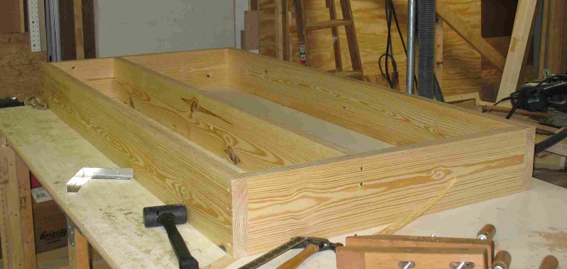
This is the beginning of the frame of the main unit top.
The same frame further along.
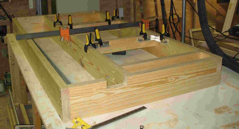
The plywood top added and the support for the Biesemeyer fence added, note that I mounted the support for the fence upside-down to get it out of the way of the saw blade.
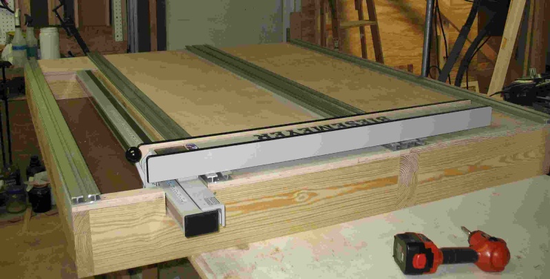
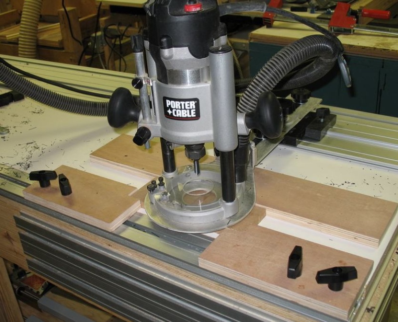
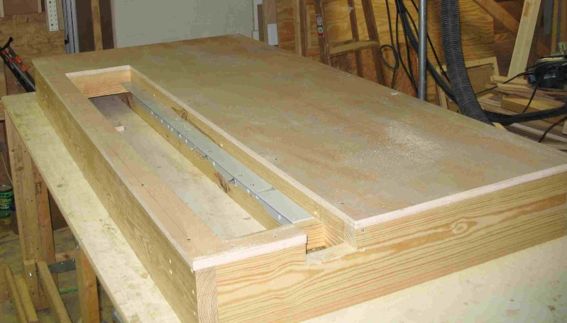
This is both top units, but the SMEs are not mounted.
Burt Wadell Posted:Dik,
Very nice start on the PBB.
As for the answer to your question, I think that it is personal preference. Try to think of things you might want to attach to the sides and route.
Would there ever be an occasion where you might want to mount the bridge across the table? If so, You would need to drop the SME a little more so that it would align properly with the bridge. Also you have been working on a number of jig designs, would any of these require a specific height?
And one final thought - if you are like most of us and mount them with pocket screws, within 5 minutes you can move them up or down to where you need them for the task at hand.
I included almost no specifics but I hope this helped.
Burt
Louis Rucci Posted:I'm curious. How is the fence used with the EZ system. I have an Incr TS-LS on my table saw and would like to incorporate into my design when I get to it.
Louis
Paul Greathouse Replied:Louis
Dik will more than likely have a bridge mounted parallel to the fence. The combination of the bridge and fence with allow for ease of repetative rips, similar to ripping stiles and rails on a tablesaw. Burt Waddell has some pictures of a table that he made with a Unisaw fence. Try searching EZ UNI.
Dik Harrison Replied:Thanks Burt,
I'm just trying to start off with a reasonable first location. I was wondering how others have their side rails mounted and what their rational was for their final location.
As for a bridge, that is the main purpose for building the PBB now. I just went back to look at Dino's instructions for setting up the bridge and I now understand that you need at least 1/4" to 1/2" between the top of the table and the top of the bridge to allow for the spacing needed for the "clamping" action of the bridge. That said, since there is a 3/4" SME at the edge of the top and I don't want to cover the side slot, so, I have that 14" to 1/2" drop covered. I should have remembered to go to the source for the answers.
Most of the designs I've worked on will mount to the top SMEs, or mount like the bridge.
After all that, I think I'll start with the side SMEs mounted just below the top SMEs.
Joe Myers Posted:Dik,
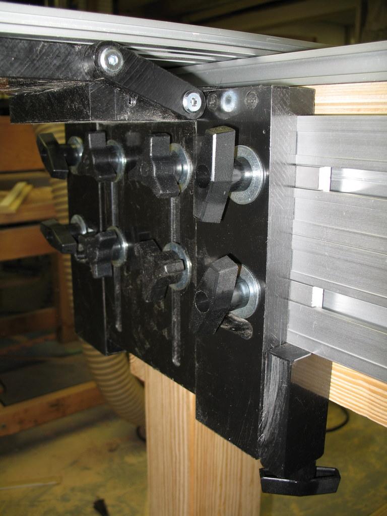
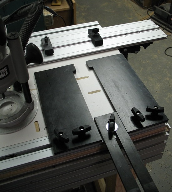
I tried a couple of locations before coming up with my current ones. But that could change once my needs change. Basically my SMEs are 1-1/4 below the bottom of the top SMEs, see phone:
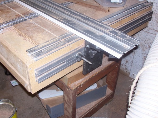
Notice that the Guide lays against the table top allowing me to cut thin plywood/wood, i.e., 1/8". If it were any higher, the Guide would not connect with the wood.
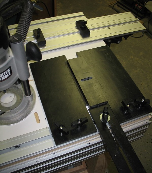
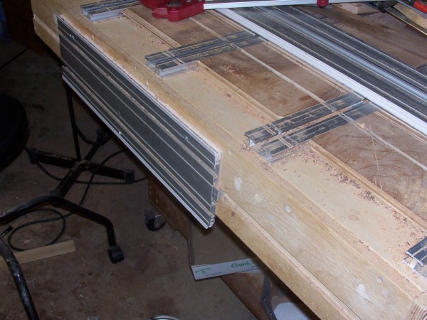
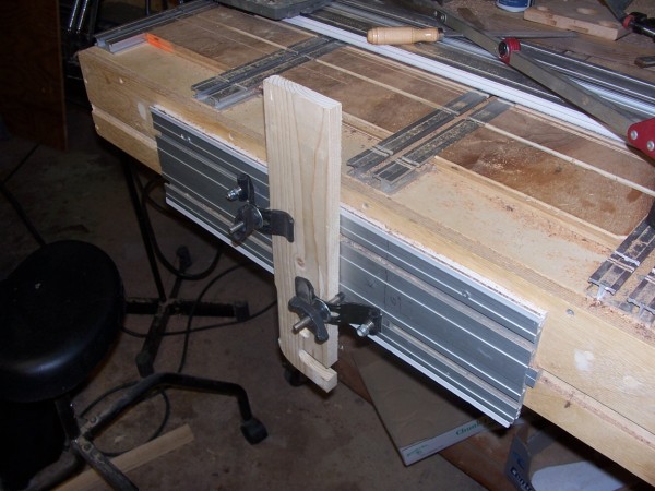
I also added a short piece of Guide, backwards, to the front (or I guess the side) to use for clamping wood, see following 3 photo's:
HTH and good luck, looking good so far,
Regards, Joe
Dik Harrison Replied:Thanks Joe,
Since I know I'll be cutting thin stock, I had better make sure the bridge will rest on the bench top when all the way down. I've noticed with the temporary setups I've done, that the bridge cannot be lowered all the way down on the slot because you can not then tighten the knobs. Guess I'll have to fiddle with that.
Louis,
Paul is correct, the fence will allow me to quickly and accurately set the desired length/width of cut. It can be lifted off when not needed and replacing it will not require realignment. I rely on the accurately set up fence on my TS almost exclusively for measuring cuts.
I will also have 3/8" thick auxiliary fence that will fasten to the regular fence and go completely under the bridge, thus allowing me to make accurate cuts that are narrower than the bridge. The auxiliary fence will be trimmed with the bridge to assure that it will be parallel to the fence.
The auxiliary fence can also be used to assure that the fence and bridge are parallel when setting up the bridge, without having to have the regular fence move all the way to the bridge. That way, the steel parts of the fence assembly are never near where the saw blade will be.
In addition, I have an INCRA miter gage that I have mounted on EZ connector that I can use in one of the top SMEs to make miter cuts.
Joe Myers Replied:Dik,
I knew I forgot something that being tightening the knobs.
Even then, I was having trouble. Turns out I had the short connectors, 2 per side, both being under the Guide. So I removed one of them per side and used a striped down version of the clamp, see picture 2 in my previous post. That gave me 3 knobs to tighten per side and eliminated the problems with the Bridge shifting on me. (Note: I'm pretty sure that the regular PBB comes with a longer connector per side so they don't have the problem I was having).
In any event, thanks for reminding me of another reason why I did what I did.
Regards, Joe
Louis Rucci Replied:Now that's interesting. I have the JessUm miter and wanted to incorporate that also. I'll be watching with interest as your PBB developes. Might have a few ideas I can use so I don't consider my previous tools purchases a waste.
Thanks,
Louis
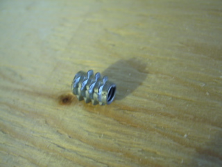
Dik Harrison Replied:I just drilled and tapped a piece of EZ connector to replace the rail that rides in the TS slot. Since the miter doesn't move, you just position it where you want it, set the angle and tighten it in place.
Louis Rucci Replied:
Neat, I'll have to take a closer look at mine and see how to incorporate that.
I haven't bought anything yet, as I keep learning more and changing my mind on what I want.
Thought I wanted the PBB 2500, then realized I can make a customized one. I now have to buckle down and determine my needs.
I haven't done any wood working, but have been collecting tools for a number of years. This past summer I had a 32'x28' shop built in my back yard.
Though I was ready and then fell into the EZ sytem by accident surfing the web last month.
Everytime I think I'm going to buy into it, something new catches my eye and changes everything.
Oh Well!, I still have time
Burt Wadell Replied:Louis,
If in doubt, order the 114 Inch set and a square. That is just enough equipment to give you an idea what the EZ can do and whit your appetite for even more!!
Burt
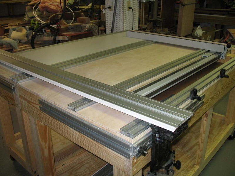
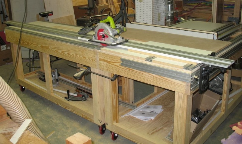
Dik Harrison Posted:It is getting there...
Still not finished, but getting close to full usability. The bases and tops are built, but still need to finish mounting rails, SMEs, and sliding modules. The pictures are with it in the 5' X 6' configuration, which is the configuration I thought I would leave it in most of the time. However, I'm already considering leaving it in the 9' X 6' "L" configuration for more versatility.
 Louis Rucci Replied:
Oh!, my order went further than that.
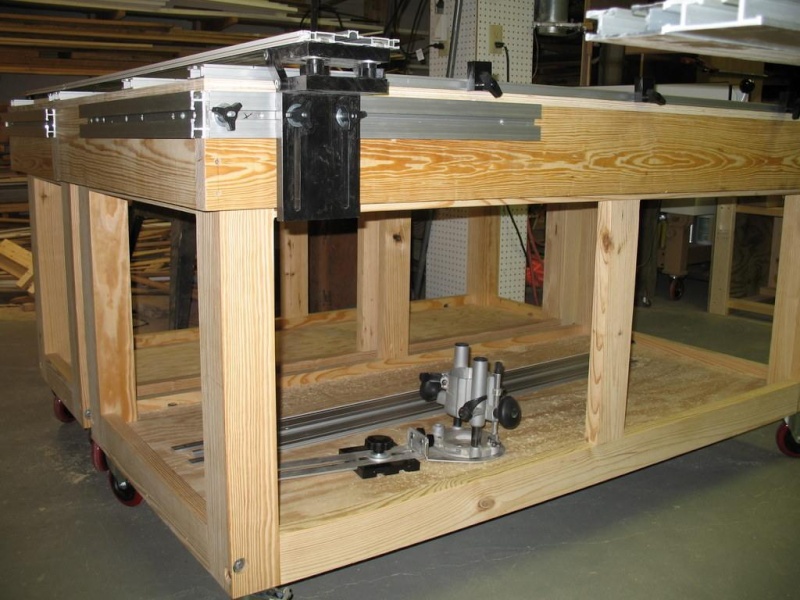
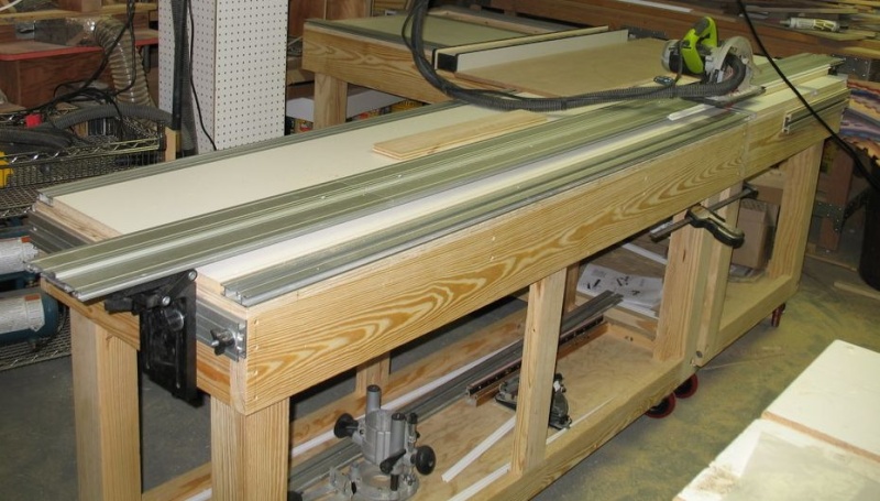
Dik Harrison Posted:  The latest installment of pics...
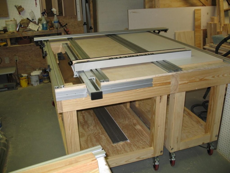
Currently I have the PBB in the 9' X 6' configuration. I think I like it best for versatility. I'll probably keep it this way until I need to straight edge long (12') boards. I can rip or cross cut a 4' X 8' sheet with this configuration Cross cut capacity goes from 0" to about 64" using the fence and its scale. it is virtually unlimited without the fence.
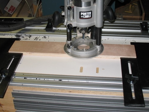
The fence is positioned about 14" back from outside edge of the rail. To make cuts between 0" and 14" I add the MDF/plywood auxiliary fence. There is a second scale that is zeroed to the auxiliary fence. Currently I am using the same cursor on the fence that is used for cuts without the auxiliary fence. Once I get another scale, I will add a second cursor to the left of the fence for the shorter cuts. That way I'll be less likely to use the wrong scale. The pencil line on the MDF in the last pic is where I will cut out to read the second scale/cursor.
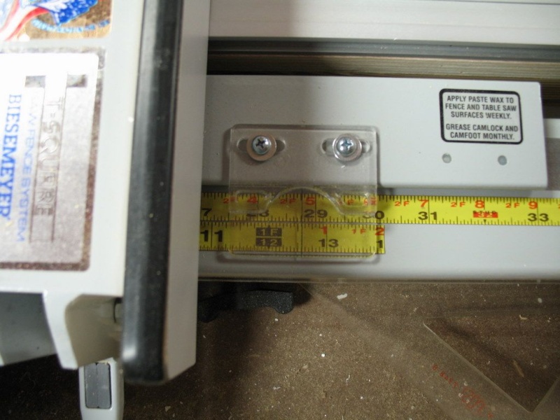
I don't have the bolts and knobs that will tighten the auxiliary fence to the fence installed yet, but when they are installed, the auxiliary fence can be slid out to extend the fence up to about 20".
Also yet to come are the bolts that will raise the table tops to align them (making up for unevenness in the floor, a way to lock the units together firmly, and additions like the M&T station, the router tunnel, line boring, surfacing setup, etc.
I am also working on a way to keep the bridge fixed in the desired location, while allowing me to raise and lower it without having to realign it. It will also allow me to have several bridge locations without having to go through the alignment process every time I move the bridge.
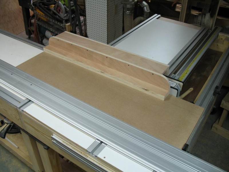
Additional Pics
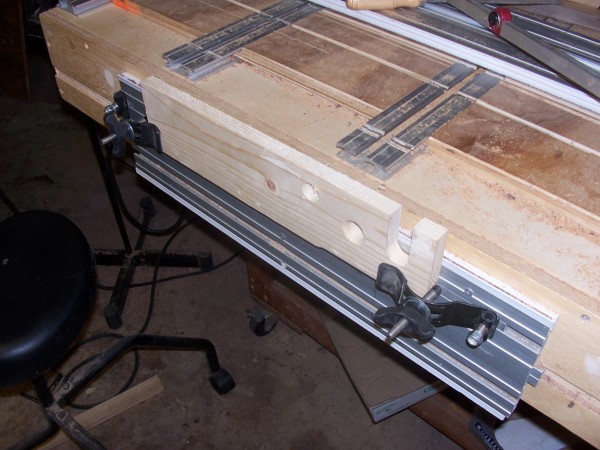
Got the bolts and knobs to fix the auxiliary fence to the fence.
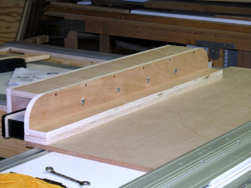
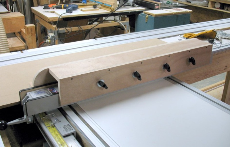
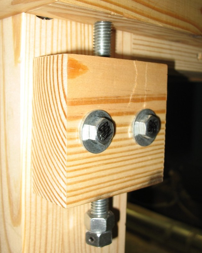
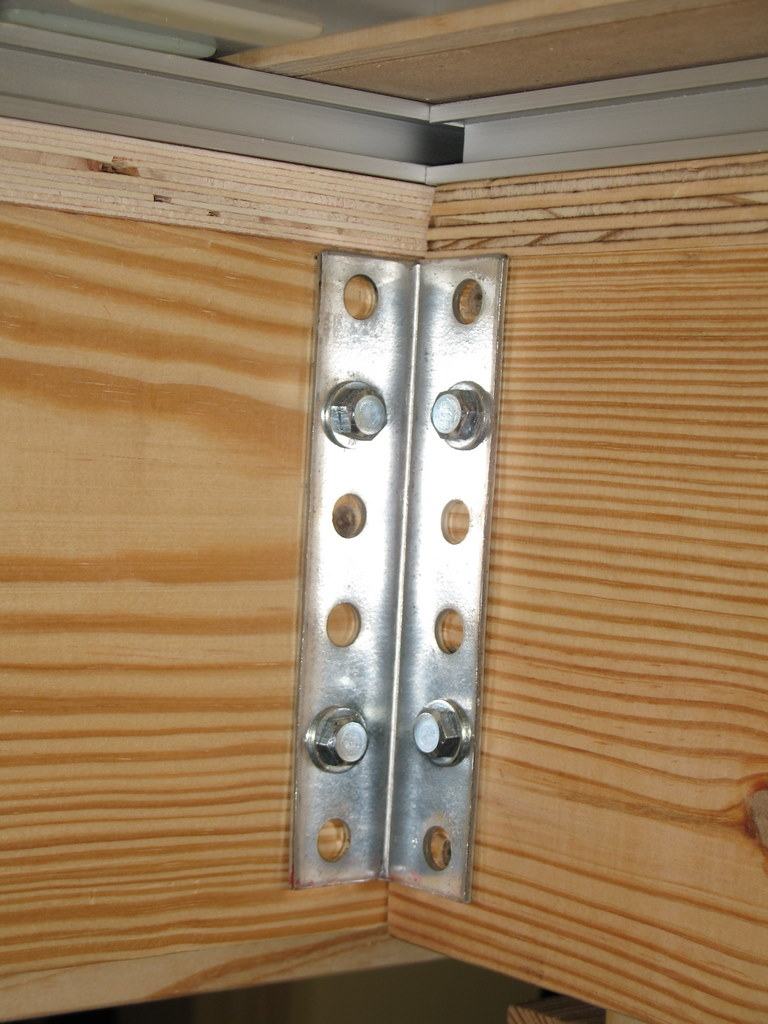
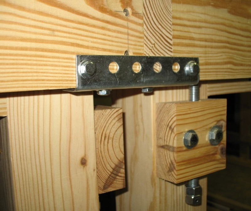
A start on the addition to the bridge. Made two connectors with four studs spaced for the bridge and one guide on each side. Once the bridge is where you want it and squared up, you tighten the guides to lock everything down. You can then loosen the knobs holding the bridge to raise or lower it without moving it out of plumb. You can also remove the knobs and washers to remove the bridge, either to relocate it or to get it out of the way. When the bridge is replaced, the guides make placing it exact, with no adjustments necessary (except for the height). The guides are out of 1/2"MDF, but will be 3/4" UHMW once I'm satisfied with the design.
 Grant McCombie Posted:
Dik
That is an excellent idea
great job, I am about to do the same
grant
Dik Harrison Replied:Thanks, I tired of having to fiddle with the alignment every time I raised or lowered the bridge. I think frustration is the stepmother of invention...
Peter West Posted:I have these on the Cabinet Makers Table and they work well. However once placed, they cannot be removed or moved if needed to attach anything else should the need arise.
To overcome this I a looking at adding two 'blocks' to the rear of the stops (your MDF pieces) and adding a fixed block screwed to the side of the table above and below the SME's. That way the the MDF stops can be removed, and when replaced the stop is positioned by the blocks on the back of the stop and on the side of the table. (I hope this makes sense).
Dik Harrison Replied:I think I get the idea. I'm not sure I have room above the SMEs for a block, but I definitely do below them. If I just put a stop below them, then the position would be replicated, and I would just have to check that the bridge guide is perpendicular to the table surface. Does that seem like a valid statement?
Peter West Replied:To save having to do that every time, as your block on the back of the stop you could use a horizontal strip which is fitted firmly up against the bottom of the SME.
That way when the stops are replaced, the block on the table and the block/strip on the rear of the stop would determine both the position and orientation. Does this sound feasible?
Dik Harrison Replied:Good idea, I had thought of putting an alignment block on top of the guide so that it would be square with the SME. I was going to put it on the top in order to make the guide adaptable to using with SMEs or with rails. An additional slot would be cut in the guide to line up with the second slot in the bottom of the rail.
Trent Flemming Posted:Hi Dik,
Really like your PBB, I keep checking your thread for great new ideas. Keep up the good work.
Trent